Installing the DXi4700 System in the Rack
Installing the DXi4700 in a rack consists of the following steps:
Component Installation Recommendations
To make it easier to correctly cable the system, and for safety reasons, follow these recommendations when installing the DXi4700 system in the rack:
-
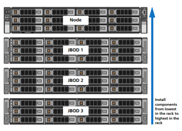
When installing components, start with the lowest Expansion module in the configuration, and then proceed upward in the rack as you add additional components.
-
Make sure to leave enough space below the lowest installed component for future system expansion. The DXi4700 can be expanded to a maximum configuration requiring 8U of rack space.
Figure 1: Recommended Component Rack Order (Maximum Configuration)
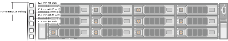
The DXi4700 system is designed to fit in a standard 19 inch (48.3 cm) wide rack. It is important for the chassis installation to locate the hole pattern in the rack rails. You must allow 2U (3.4 inches or 8.7 cm) of vertical space for the DXi4700 Node and an addition 2U for each Expansion module (JBOD) installed in the rack.
Rack cabinets that meet EIA-310 standards have an alternating pattern of three holes per rack unit with center-to-center hole spacing (beginning at the top hole of a 1U space) of 15.9 mm, 15.9 mm, and 12.7 mm (0.625 inch, 0.625 inch, and 0.5 inch) for the front and back vertical rails (see Figure 2). Rack cabinets may have round or square holes. For more information, refer to the DXi4700 Site Planning Guide.
WARNING: If the rack is empty at the time of installation, do NOT install the DXi4700 chassis too high in the rack. The weight of the chassis may cause the rack to become “top heavy” and unstable if installed in the top of an empty rack.
To mark the rack, place a mark (or tape) on the rack’s front vertical rails where you want to locate the bottom of the unit you are installing in the rack. The bottom of each 1U space is at the middle of the narrowest metal strip between holes (marked with a horizontal line on some rack cabinets).
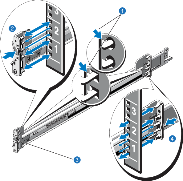
- Position the left and right rail end pieces labeled FRONT facing inward, and orient each end piece to seat in the holes on the front side of the vertical rack flanges (see Figure 3).
- Align each back end piece in the bottom and top holes of the desired U spaces.
- Engage the back end of the rail until it fully seats on the vertical rack flange and the latch clicks into place. Repeat these actions to position and seat the front end piece on the vertical rack flange.
Figure 3: DXi4700 Expansion Module Rails Installation
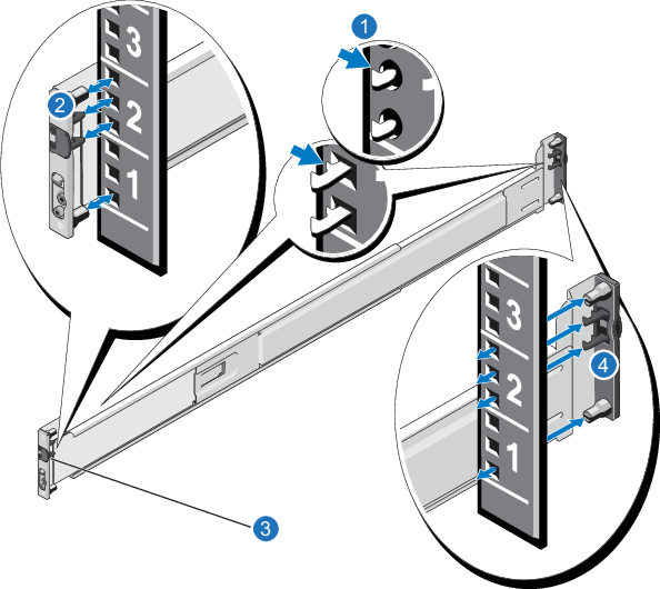
| Item | Description |
|---|---|
| 1 | Latches click into place in rack flange (round or square holes). |
| 2 | Rail front end. |
| 3 | Latch release button. |
| 4 | Rail back end. |
WARNING: The DXi4700 Expansion module (JBOD, including hard drives) weighs 62.6 pounds (28.4 kg). A minimum of two people are required to lift the chassis. To lift the chassis, use the slots in the packing foam to place your hands under the sides of the chassis.
Caution: Before proceeding, ensure that all hard drive latches are completely closed. Quantum recommends that you do not remove the hard drives from the chassis. If they have been removed for any reason during or after the installation, you must install the hard drives in the same position in which they were removed.
- Align the Expansion module with the rails, and then slide the module into the rack.
-
Tighten the thumbscrews on each side of the Expansion module’s front panel.
Note: To remove the Expansion module, loosen the thumbscrews and slide the Expansion module out of the rack.
-
Install the end caps on either side of the module by inserting the top of the end cap first and then snapping the bottom into place.
Install the end cap with the indicator icons to the left of the module, and install the end cap with the drive numbers to the right of the module.
Note: To remove the Expansion module, remove the screws and slide the module out of the rack.
Figure 4: DXi4700 Expansion Module Installation
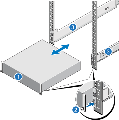
| Item | Description |
|---|---|
| 1 | Front of Expansion Module |
| 2 | Thumbscrew |
| 3 | Rails |
-
Position the left and right rail end pieces labeled FRONT facing inward, and orient each end piece to seat in the holes on the front side of the vertical rack flanges.
Make sure to align the pins correctly with the holes, as inserting them in the wrong holes may bend them. The top of the rail front end should be flush with the desired line on the vertical rack flange.
- Align each back end piece in the bottom and top holes of the desired U spaces.
- Engage the back end of the rail until it fully seats on the vertical rack flange and the latch clicks into place. Repeat these actions to position and seat the front end piece on the vertical rack flange.
Removing the Rails
If you need to remove the rails, use a flat head screwdriver to lift the latch release button on the end piece midpoint and unseat each rail.
Figure 5: Node Rails Installation
| Item | Description |
|---|---|
| 1 | Latches click into place in rack flange (round or square holes) |
| 2 | Rail front end |
| 3 | Latch release button |
| 4 | Rail back end |
WARNING: The DXi4700 G1 Node and Expansion module (JBOD) weigh 61.0 pounds (27.7 kg) and 62.6 pounds (28.4 kg) respectively. A minimum of two people are required to lift either chassis.
WARNING: The DXi4700 G2 Node and Expansion module (JBOD) weigh 49.4 pounds (22.4 kg) and 59.2 pounds (26.8 kg) respectively. A minimum of two people are required to lift either chassis.
Caution: Before proceeding, ensure that all hard drive latches are completely closed. Quantum recommends that you do not remove the hard drives from the chassis. If they have been removed for any reason during or after the installation, you must install the hard drives in the same position in which they were removed.
- Pull the inner slide rails out of the rack until they lock into place.
- Locate the rear rail standoff on each side of the system and lower them into the rear J-slots on the slide assemblies.
- Rotate the Node downward until all the rail standoffs are seated in the J-slots.
- Press the slide-release lock buttons on both rails and slide the system into the rack. (Make sure the Node is squarely aligned with the rack as you slide it in.)
Note: To remove the Node, locate the lock levers on the sides of the inner rails. Unlock each lever by rotating it up to its release position. Grasp the sides of the system firmly and pull it forward until the rail standoffs are at the front of the J-slots. Lift the system up and away from the rack and place it on a level surface.
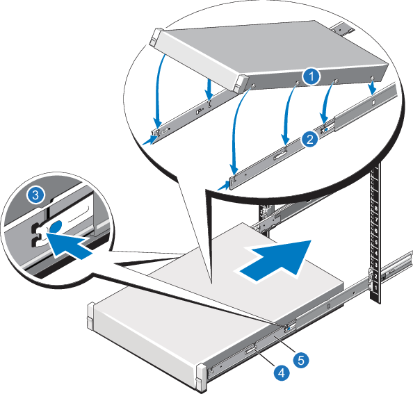
| Item | Description |
|---|---|
| 1 | Rear rail standoffs |
| 2 | Rear rail J-slots |
| 3 | Slide-release lock button |
| 4 | Lock lever |
| 5 | Inner slide rails |
Follow these steps to cable the DXi4700:
-
Connect each Array module (RBOD) to the DXi4700 Node.
- For DXi4700 G1 models, (see Table 1).
- For DXi4700 G2 models, (see Table 2).
Table 1: Connecting the DXi4700 G1 Expansion Modules (JBODs)
| Node | JBOD 1 | JBOD 2 | JBOD 3 |
|---|---|---|---|
|
SAS port 1 (left) |
Primary SAS In port (top) |
||
|
SAS port 2 (right) |
Secondary SAS In port (bottom) |
||
|
Primary SAS Out port (top) |
Primary SAS In port (top) |
||
|
Secondary SAS Out port (bottom) |
Secondary SAS In port (bottom) |
||
|
Primary SAS Out port (top) |
Primary SAS In port (top) |
||
|
Secondary SAS Out port (bottom) |
Secondary SAS In port (bottom) |
Table 2: Connecting the DXi4700 G2 Expansion Modules (JBODs)
| Node | JBOD 1 | JBOD 2 | JBOD 3 |
|---|---|---|---|
| SAS port 1 (left) | Primary SAS In port 1 (top) | ||
| SAS port 2 (right) | Secondary SAS In port 1 (bottom) | ||
| Primary SAS port 2 (top) | Primary SAS port 1 (top) | ||
| Secondary SAS port 2 (bottom) | Secondary SAS port 1 (bottom) | ||
| Primary SAS port 2 (top) | Primary SAS port 1 (top) | ||
| Secondary SAS port 2 (bottom) | Secondary SAS port 1 (bottom) |
- Do not connect any Ethernet cables at this time. (You will connect them in a later procedure.)
-
(VTL and Multi-Protocol configurations only) Connect Fibre Channel cables to each Fibre Channel port in slot 3. Fibre Channel ports 0 and 1 are used for virtual tape library (VTL) host connection.
-
(Multi-Protocol only) Connect Fibre Channel cables to each Fibre Channel port in slot 2. Fibre Channel ports 2 and 3 are used for Path-to-Tape (PTT) connections.
Note: If there is port cover on the port, remove it before connecting a cable.
-
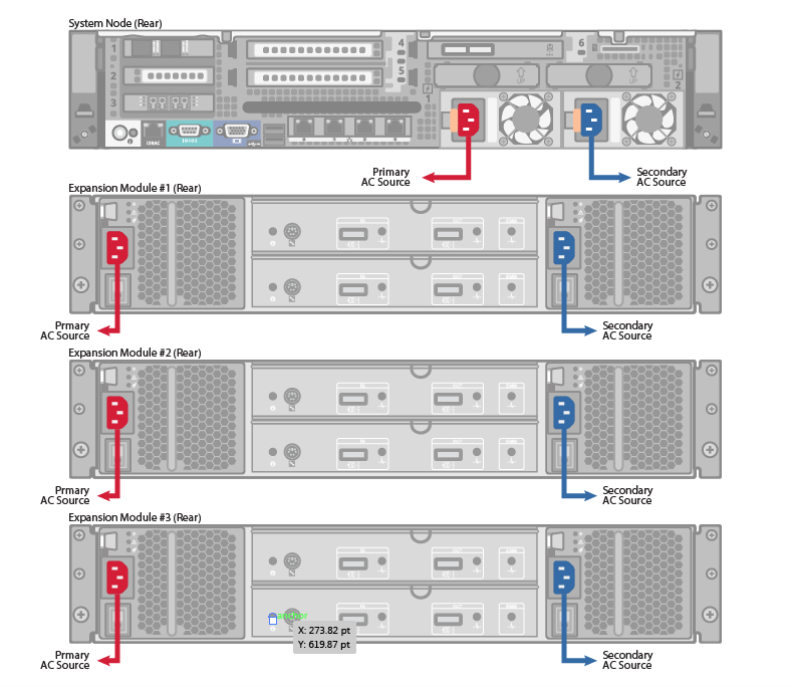
Connect each power supply to a primary and secondary AC power source using the provided power cables. Use the attached straps to secure the power cords to the chassis.
Note: Quantum recommends connecting each power cord to a separate AC circuit to ensure system availability in case of a power failure. Power supplies should be checked periodically for audible and LED warnings.
Figure 7: DXi4700 G1 SAS Cabling
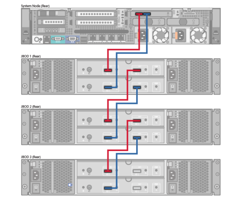
Figure 8: DXi4700 G2 SAS Cabling
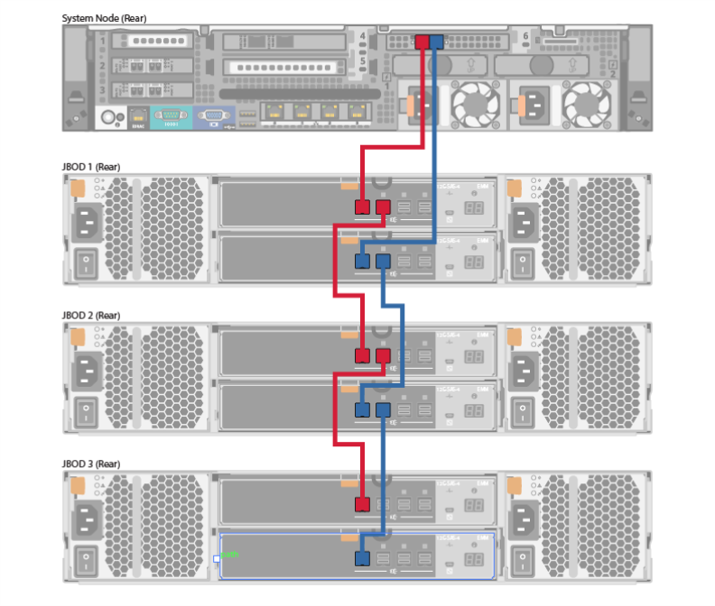
Figure 9: DXi4700 Fibre Channel Cabling (VTL/PTT Configurations Only)
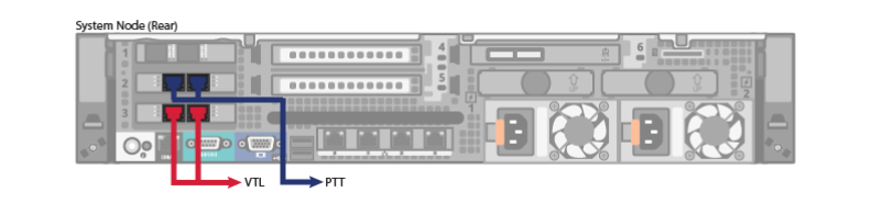
Figure 10: DXi4700 Power Cabling